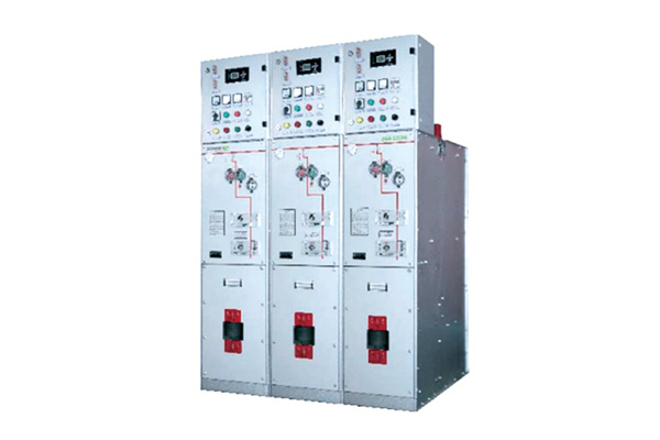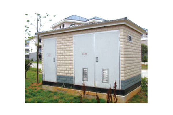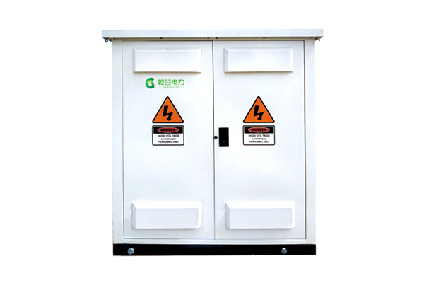
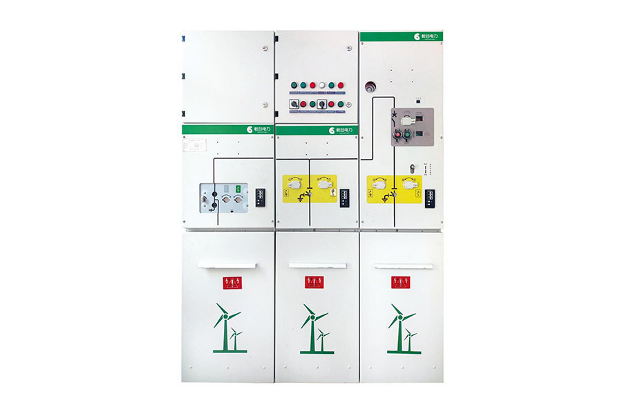
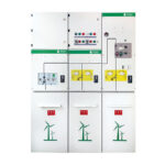
· This product is designed and manufactured in compliance with GB and IEC standards.
· Manufactured with a structural design featuring vacuum arc-extinguishing and all-insulated by SF6 gas;
· The gas container’s protection rating reaches IP67, and it operates without failure throughout the installation process and its entire service life, requiring no refilling or recharging of gas.
· The product meets requirements for altitudes of 5,000 meters and below;
· Suitable for operation in environments with industrial pollution, salt spray, and high humidity; meets C3 standard on land and C4 standard at sea.
Altitude: ≤5000m (When the operating altitude of the equipment exceeds 2000m, this must be specifically noted);
Ambient temperature: Maximum temperature +50℃, minimum temperature -50℃, average value within 24 hours ≤35℃;
Environmental humidity: Average relative humidity over 24 hours ≤ 95%; average monthly relative humidity ≤ 90%.
Electromagnetic interference: The amplitude of electromagnetic interference induced in the secondary system ≤ 1.6 kV;
Installation environment: The surrounding air contains neither explosive nor corrosive gases, and the installation location is free from frequent, severe vibrations or shocks.
Note: If the operating environment conditions exceed those specified above, please consult our company to arrange a custom solution.
IEC 62271-1:2017 and GB/T 11022-2020 – Common Technical Requirements for High-Voltage Switchgear and Control Equipment
IEC62271-200:2011 and GB/T3906-2020 3.6kV~40.5kV AC metal-enclosed switchgear and control equipment
IEC62271-100:2017 vs. GB/T1984-2014 — AC High-Voltage Circuit Breakers
IEC 62271-105:2021 and GB/T 16926-2009—AC High-Voltage Load Break Switch-Fuse Combination Apparatus
IEC16271-102:2001+A1:2011 and GB/T1985-2014—High-voltage AC isolating switches and earthing switches
IEC60529 and GB/T4208-2017: Enclosure Protection Ratings (IP Codes)
GB/T11023-2018 Test Method for Gas Sealing of Sulfur Hexafluoride in High-Voltage Switchgear
DL/T402-2016 Technical Specifications for Ordering High-Voltage AC Circuit Breakers
DL/T486-2021 Technical Specifications for Ordering High-Voltage AC Disconnect Switches and Earthing Switches
DL/T403-2017 12kV~40.5kV High-Voltage Vacuum Circuit Breakers — Technical Specifications for Ordering
DL/T404-2018 3.6 kV to 40.5 kV AC Metal-Enclosed Switchgear and Control Equipment
DL/T593-2016 Common Technical Requirements for High-Voltage Switchgear and Control Equipment Standards
Qian Gu Power is committed to environmental protection. Its products have obtained ISO 14001 international environmental management system certification and strictly adhere to this standard.
Recycling and Disposal
The UN3 series switchgear is designed and manufactured in compliance with the national standard GB/T 3906 and the international standard IEC 62271-200. At the end of the product’s lifecycle, SF6 gas will be recovered and reused in accordance with relevant standards.
Sustainable development
The UN3 series switchgear continuously reduces the use of SF6 during the manufacturing process and does not use SF6 gas during installation.
All products are made from 100% recyclable materials.
Provide self-powered relays and devices to avoid additional energy consumption.
1. Secondary Control Room: Located at the upper front of the switchgear cabinet, with a protection rating of up to IP4X.
2. Analog busbar: Accurately indicates the wiring configuration of the primary circuit.
3. Pressure Relief Channel: The pressure relief channel is located at the bottom of the switchgear cabinet. It allows arc gases generated in the gas chamber or cable compartment to be vented through the pressure relief channel at the bottom of the cabinet into the cable trench, thereby ensuring the safety of operating personnel.
4. Busbar connection: Under normal operating conditions, the rated current shall be 1.1 times the rated current of 630A.
5. Circuit Breaker and Mechanism: The circuit breaker is equipped with a spring-operated mechanism and features automatic reclosing functionality. It can be manually or electrically energized, and supports remote signaling, remote control, and remote measurement.
6. Disconnecting switch and operating mechanism: Can be operated manually or electrically, and can be controlled either on-site or remotely.
7. Cable Connection and Surge Arrester Installation: Install and maintain cables and their accessories from the front of the cabinet, with an installation height of 600 mm or 700 mm. This installation method is suitable for various specifications of single-core or three-core cables.

|
Operating continuity levels defined in GB/T 3906 |
||||
|
Other high-voltage compartments or functional units remain energized. |
LSC 1: Lower service continuity |
|
LSC 1 | LSC 2 |
|
LSC 2: Higher Service Continuity |
|
|
● | |
|
Partition between compartments |
PI: Insulating partition |
|
PI |
PM |
|
PM: Metal Grounding Baffle |
|
|
● | |
|
Insulation and Switching |
||||
|
Main circuit disconnection |
|
|
Vacuum circuit breaker |
|
|
Interrupting medium |
|
|
Vacuum arc-extinguishing chamber |
|
|
Insulating medium |
|
|
SF6 gas | |
|
Relative inflation pressure |
Rated inflation pressure (gauge pressure at 20℃) |
MPa |
0.04 |
|
|
Minimum inflation pressure (gauge pressure at 20℃) |
MPa |
0.02 |
||
|
Annual relative leakage rate of gas |
|
%/year |
≤0.01 |
|
|
Insulation level |
||||
|
Rated voltage |
|
kV |
36/40.5 | |
|
Rated frequency |
|
Hertz |
50 |
|
|
Rated insulation level |
Power-frequency withstand voltage (phase-to-phase, phase-to-ground, vacuum interrupter contacts) |
kV |
70/95 | |
|
Power-frequency withstand voltage (isolated break) |
kV |
80/118 | ||
|
Power-frequency withstand voltage (auxiliary and control circuits) |
kV |
2 |
||
|
Lightning impulse withstand voltage (phase-to-phase, phase-to-ground, vacuum interrupter) |
kV |
170/185 |
||
|
Lightning Impulse Withstand Voltage (Isolation Break) |
kV |
195/215 | ||
|
Current level |
||||
|
Rated current—busbar |
A |
630 |
||
|
Rated short-circuit breaking current |
kA |
25/31.5 | ||
|
Rated short-circuit making current (main switch/grounding switch) |
kA |
63/54. 3, 80/69.6 |
||
|
Short-time withstand current and duration (main circuit + earthing switch, earthing connection) |
kA/s | 25/4, 31.5/4 | ||
|
Rated peak withstand current (main circuit + earthing switch, earthing connection) |
kA |
63/80 |
||
|
Internal arc fault withstand capability |
||||
|
Grade A |
A FL front and side views |
kA |
25/31.5 | |
|
Duration |
S |
1 | ||
|
Enclosure protection rating |
||||
|
Complies with GB/T4208 standard enclosure protection. |
An energized electrical box |
|
IP67 |
|
|
Cable Room |
|
IP43 |
||
|
Institutional Room |
|
IP4X |
||
|
Low-pressure room |
|
IP4X |
||
|
Mechanical impact protection rating |
||||
|
Grade compliant with GB/T 20138 |
|
IK07 | ||
|
Other features |
||||
|
Expected service life |
Year |
30 |
||
|
Busbar/Grounding busbar (copper bar) |
|
120 mm² |
||