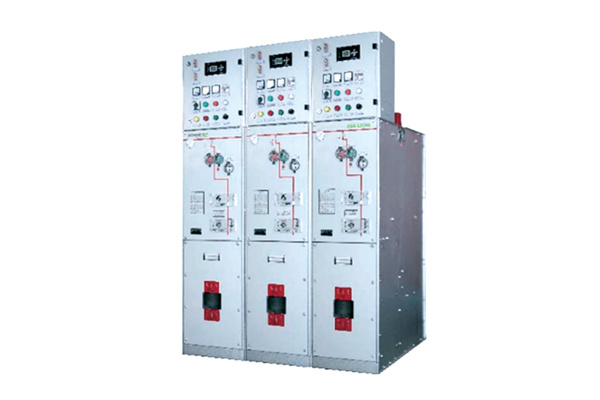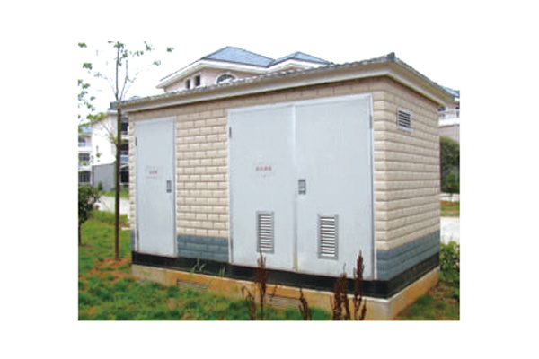
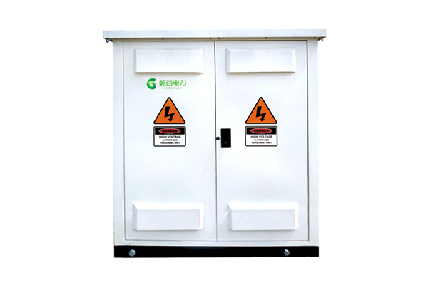
The enclosure is welded from stainless steel, and all sheet-metal joints feature a waterproof sealing design.
Optional fully insulated SF6 load switch solution, equipped with touchable shielded T-type cable accessories and surge arresters. Each ring main unit line can be fitted with a load switch, allowing any branch circuit to be freely disconnected or put into operation at any time. Other rings…
The network circuit is unaffected.
(1) Anti-fouling and moisture-proof
The roof, side panels, and doors of the outdoor switchgear cabinet (cable distribution box) feature a rainproof structural design.
Suitable for operation in environments with industrial pollutants, salt content, and high humidity.
Outdoor cubicle switchgear (cable distribution box): Corrosion protection rating—onshore: C4; offshore: C4H.
(2) Ground continuity
The primary circuit and secondary circuit grounding are connected separately to the grounding grid.
The enclosure of outdoor switchgear cabinets (cable distribution boxes), as well as touchable doors and side panels, feature good grounding continuity, effectively ensuring personnel safety.
Altitude: S ≤ 5,000 m (Please specify explicitly if the device is operated at an altitude exceeding 2,000 m);
Ambient temperature: Maximum temperature +50℃, minimum temperature -50℃, average value over 24 hours: 35°C.
Environmental humidity: The 24-hour average relative humidity is 95%; the monthly average relative humidity is 90%.
Electromagnetic interference: The amplitude of electromagnetic interference induced in the secondary system is 1.6 kV;
Installation environment: The surrounding air contains no explosive or corrosive gases, and the installation location is free from frequent, severe vibrations or shocks.
Note: If the operating environment conditions exceed those specified above, please consult our company to arrange a customized solution.
GB/T 3906-2020 3.6kV~40.5kV AC Metal-Enclosed Switchgear and Control Equipment
GB/T 11022-2020 Common Technical Requirements for High-Voltage Switchgear and Control Equipment (IEC 62271-1:2007 MOD)
JB/T10840-2019 3.6kV~40.5kV High-Voltage AC Metal-Enclosed Cable Tap Switchgear
GB11033.2-1989 Basic Technical Requirements for Power Cable Accessories Rated 26/35 kV and Below
GB/T17467-2020 High-Voltage/Low-Voltage Prefabricated Substation
Qian Gu Electric is committed to environmental protection. Its products are certified under the ISO 14001 international environmental management system and strictly adhere to this standard.
Recycling and Disposal
The design and manufacture of UN3W switchgear (branch boxes) comply with the requirements of the national standard JB/T10840. At the end of the product’s lifecycle, they will be recycled and reused in accordance with relevant standards.
Sustainable development
The installation process does not use SE6 gas: all products are made from 100% recyclable materials; self-powered relays and devices are provided to avoid additional energy consumption.

|
The operational continuity levels defined in GB/T 17467 |
|||||
|
Other high-voltage compartments or functional units remain energized. |
LSC 1: Lower service continuity |
|
LSC 1 |
LSC 2 | |
|
LSC 2: Higher Service Continuity |
|
|
● | ||
|
Partition between compartments |
PI: Insulating partition |
|
PI | PM | |
|
PM: Metal Grounding Baffle |
|
|
● | ||
|
Insulation level |
12 | 24 | 40.5 | ||
|
Rated voltage |
|
kV |
12 |
24 |
40.5 |
|
Rated frequency |
|
Hertz |
50 |
50 |
50 |
|
Rated insulation level |
Power-frequency withstand voltage (phase-to-phase, phase-to-ground, vacuum interrupter contacts) |
kV |
42 |
65 |
95 |
|
Power-frequency withstand voltage (isolated break) |
kV |
48 |
79 |
118 |
|
|
Power-frequency withstand voltage (auxiliary and control circuits) |
kV |
2 |
2 |
2 |
|
|
Lightning impulse withstand voltage (phase-to-phase, phase-to-ground, vacuum interrupter) |
kV |
75 |
125 |
185 |
|
|
Lightning Impulse Withstand Voltage (Isolation Break) |
kV |
85 |
145 |
215 |
|
|
Current level |
12 |
24 |
40.5 |
||
|
Rated current—busbar |
kA |
630 |
630 |
630 |
|
|
Rated short-circuit breaking current |
kA |
25 |
25 |
25 |
|
|
Rated short-circuit making current (main switch/grounding switch) |
kA |
63/63 |
63/63 |
63/63 | |
|
Short-time withstand current and duration (main circuit + earthing switch, earthing connection) |
kA/s |
25/17.6 |
25/17.6 |
25/17.6 |
|
|
Rated peak withstand current (main circuit + earthing switch, earthing connection) |
kA |
63/54 |
63/54 |
63/54 |
|
|
Internal arc fault withstand capability |
|||||
|
Grade B |
B FL Front and side |
kA |
20 |
||
|
B FLR Front, side, and rear |
kA |
20 |
|||
|
Duration |
S |
1 |
|||
|
Enclosure protection rating |
|||||
|
Enclosure protection conforming to GB/T 4208 standard |
An energized electrical box |
|
IP67 |
||
|
Cable Room |
|
IP43 |
|||
|
Institutional Room |
|
IP4X |
|||
|
Low-pressure room |
|
IP4X |
|||
|
Mechanical impact protection rating |
|||||
|
Grade compliant with GB/T 20138 |
|
IK07 |
|||
|
Other features |
|||||
|
Expected service life |
Year |
30 |
|||
|
Busbar/Grounding busbar (copper bar) |
|
300mm2 |
|||
|
Model Specifications |
Rated Voltage (kV) |
Rated Voltage (A) | Cable cross-section (mm²) 2) | |
| Minimum value (mm) | Maximum value (mm) | |||
|
SLKCTH-33/□/□ |
36 |
630 (1250) |
35 |
630 |
|
SLKCTH-35/□/□ |
40.5 |
630(1250) |
35 |
630 |
|
Inner hole of stress cone Diameter Specification (mm) |
Cable core insulation diameter range |
19/33 (36) kV |
26/35 (40.5) kV | 20.8/36 (42) kV | |
| Minimum value (mm) | Maximum value (mm) | Cable cross-section (mm²) 2) | Cable cross-section (mm²) 2) | Cable cross-section (mm²) 2) | |
|
Φ19 |
Φ22 |
Φ24 |
25-50 |
|
|
| Φ23 |
Φ25 |
Phi 29.5 |
35-95 |
25-35 |
25-50 |
|
Φ26 |
Φ30 |
Φ35 |
120-185 |
50-70 |
70-120 |
|
Φ30 |
Φ35 |
Φ38 |
240-300 |
95-120 |
150-185 |
|
Φ34 |
Φ38 |
Φ42 |
400 |
150-240 |
240-300 |
|
Φ38 |
Phi 44 |
Φ48 |
500-630 |
300-400 |
400-500 |
|
Φ42 |
Φ49 |
Phi 54 |
800 |
500-630 |
630 |
|
Model Name |
SLK1250T-51/134 |
Other custom models |
|
System Nominal Voltage (kV) |
35 |
|
|
Rated Voltage (kV) |
51 |
|
|
Continuous operating voltage (kV) |
40.8 |
|
|
Residual voltage under lightning impulse current (kV) |
≤134 |
|
|
Voltage U1mA at 1mA DC ≥ (kV) |
73 |
|
|
Leakage current at 0.75U1mA ≤ (μA) |
50 |
|
|
2ms Square Wave Impact Capacity (A) |
600 |
|
|
Power-frequency withstand voltage of composite insulation jacket (kV/5 min) |
95 |
|
|
Partial discharge (≤10 pC) corresponding voltage |
45 |
; |