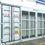
1. Anti-fouling and moisture-resistant
The top plate of the box-type substation, the side panels of the enclosure, and the doors are designed with rainproof structures.
Suitable for operation in environments with industrial pollutants, salt content, and high humidity.
Switchgear corrosion protection level: Onshore reaches C4, offshore reaches C4H.
All secondary component connections use moisture-proof, damp-proof, and mold-resistant connectors.
2. Continuous grounding
· The primary circuit ground and the secondary circuit ground shall be connected separately to the grounding grid.
The enclosure’s outer shell, touchable doors, side panels, and other components have good grounding continuity, effectively ensuring personnel safety.
3. Arc-extinguishing design
The pressure-relief channels for the switchgear’s gas compartment and cable room are designed at the bottom of the cabinet, directing pressure relief toward the cable trench.
The inner walls of the gas-insulated switchgear and cable compartments all adopt a special design featuring arc-resistant properties.
The enclosure strength meets the requirements of the arc-flash test.
4. Intelligentization
· Provide intelligent solutions to facilitate digital upgrades.
· Provides online monitoring of switch status, mechanical characteristics, vacuum status, humidity, and partial discharge. Monitoring function
Real-time online monitoring of IT and OT technologies
Meets remote operation, monitoring, and management functions.
You can obtain the installation and usage instructions for the box-type substation via a QR code.
Altitude: ≤5000m (When the operating altitude of the equipment exceeds 2000m, this must be specifically noted);
Ambient temperature: Maximum temperature +50℃, minimum temperature -50℃, average value within 24 hours ≤35℃;
Environmental humidity: Average relative humidity over 24 hours ≤ 95%; average monthly relative humidity ≤ 90%.
Electromagnetic interference: The amplitude of electromagnetic interference induced in the secondary system ≤ 1.6 kV;
Installation environment: The surrounding air contains no explosive or corrosive gases, and the installation location is free from frequent, severe vibrations or impacts.
Note: If the operating environment conditions exceed those specified above, please consult our company to arrange a customized solution.
· GB/T 17467-2020 High-Voltage/Low-Voltage Prefabricated Substation
· GB/T 1094.1-2013 Power Transformers—Part 1: General Requirements
· GB/T 1094.2-2013 Power Transformers—Part 2: Temperature Rise
· GB/T 1094.3-2017 Power Transformers—Part 3: Insulation Tests, Insulation Coordination, and External Air Clearances
· GB/T 3906-2020 3.6kV~40.5kV AC Metal-Enclosed Switchgear and Control Equipment
· GB/T 11022-2020 Common Technical Requirements for High-Voltage Switchgear and Control Equipment
· GB/T 7251.1-2016 Low-voltage switchgear and controlgear assemblies—Part 1: General rules
· GB/T 14048.1-2016 Low-voltage switchgear and controlgear — Part 1: General rules
Qian Gu Electric is committed to environmental protection. Its products are certified under the ISO 14001 international environmental management system and strictly adhere to this standard.
Recycling and Disposal
The design and manufacture of the YB27 substation comply with the national standard GB/T17467. At the end of the product’s lifecycle, it will be recycled and reused in accordance with relevant standards.
Sustainable development
The YB27 substation continuously reduces SF6 emissions during the manufacturing process and does not use SF6 gas during installation.
All products are made from 100% recyclable materials;
Provide self-powered relays and devices to avoid additional energy consumption.
|
Operation continuity defined in B/T17467 |
||||
|
Other high-voltage compartments or functional units remain energized. |
LSC 1: Lower service continuity |
|
LSC 1 |
LSC 2 |
|
LSC 2: Higher Service Continuity |
|
● |
||
|
Partition between compartments |
PI: Insulating partition |
|
PI |
PM |
|
PM: Metal Grounding Baffle |
|
● |
||
|
Insulation level |
||||
|
Main circuit disconnection |
|
Vacuum circuit breaker |
||
|
Interrupting medium |
|
Vacuum arc-extinguishing chamber |
||
|
High-voltage side |
Low-pressure side |
|||
|
Rated voltage |
|
kV |
40.5 |
0.69/2 * 0.27 |
|
Rated frequency |
|
Hertz |
50, 60 |
50, 60 |
|
Rated insulation level |
Power-frequency withstand voltage (phase-to-phase, phase-to-ground, vacuum interrupter contacts) |
kV |
95 |
2 |
|
Power-frequency withstand voltage (isolated break) |
kV |
118 |
2 |
|
|
Power-frequency withstand voltage (auxiliary and control circuits) |
kV |
2 |
2 |
|
|
Lightning impulse withstand voltage (phase-to-phase, phase-to-ground, vacuum interrupter) |
kV |
185 |
6 |
|
|
Lightning impulse withstand voltage (isolated break) |
kV |
215 |
6 |
|
|
Current level |
High-voltage side |
Low-pressure side |
||
|
Rated current—busbar |
A |
630 |
6300 |
|
|
Rated short-circuit breaking current |
kA |
25 |
50 |
|
|
Rated short-circuit making current (main switch/grounding switch) |
kA |
63/63 |
125 |
|
|
Short-time withstand current and duration (main circuit + earthing switch, earthing connection) |
kA/S |
25/17.6 |
50/43.5 |
|
|
Rated peak withstand current (main circuit + earthing switch, earthing connection) |
kA |
63/54 |
125/109 |
|
|
Internal arc fault tolerance |
||||
|
Grade B |
B FL Front and side |
kA |
20 |
|
|
B FLR Front, side, and rear |
kA |
20 |
||
|
Duration |
S |
1 |
||
|
Enclosure protection class |
||||
|
Protection rating |
Cable Room |
|
IP43 |
|
|
Institutional Room |
|
IP4X |
||
|
Low-pressure room |
|
IP4X |
||
|
Mechanical impact protection rating |
||||
|
Grade compliant with GB/T20138 |
|
IK07 |
||
|
Other features |
||||
|
Expected service life |
Year |
30 |
||
|
Busbar/grounding busbar (copper bar) |
|
300mm2 |
||