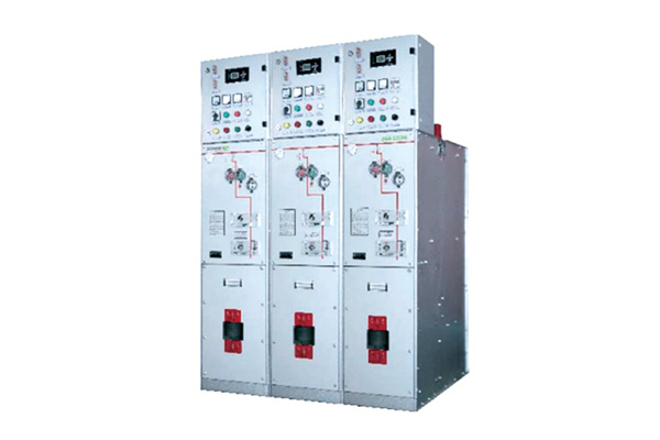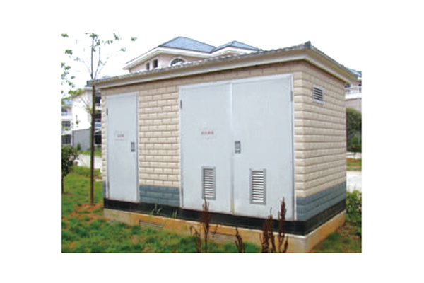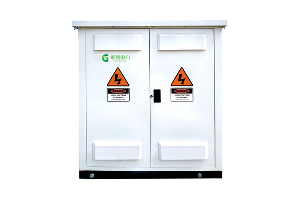
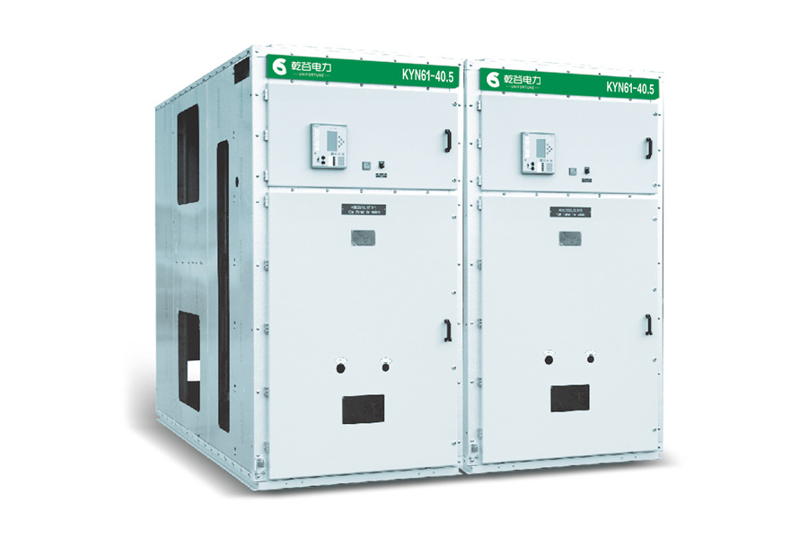
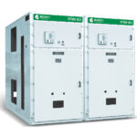
The KYN61-40.5(Z) armored withdrawable AC metal-clad switchgear (hereinafter referred to as the switchgear) is a product developed by Shanghai Qianggu Electric Technology Co., Ltd. Its main features include the use of a new type of fully insulated vacuum circuit breaker inside the cabinet, and an assembled cabinet structure that enhances the product’s aesthetic quality and improves the precision of fit between the handcart and the cabinet body. The handcart can be pushed in and pulled out with remarkable ease, ensuring interchangeability. Moreover, this design facilitates rapid production and assembly, enables timely delivery, maximizes the utilization of space required for assembly, and makes it easy to scale up for mass production.
Closed-door operation is achievable. All normal operations—including the opening and closing of circuit breakers, the pushing of circuit breaker trolleys into the working position and withdrawing them to the test/isolation position, as well as the opening and closing of grounding switches—can be performed with the circuit breaker room door closed.
Complies with standards: GB3906, GB/T11022, IEC62271-200.

Ambient temperature: -15℃ to +40℃
Altitude: Standard cabinet models are suitable for altitudes not exceeding 1,000 meters; high-altitude models are designed to meet requirements at altitudes up to 3,000 meters.
Relative humidity of air: The daily average shall not exceed 95%, and the monthly average relative humidity shall not exceed 90%.
Seismic intensity: not exceeding 8 degrees
Places free from obvious contamination by corrosive or flammable gases, water vapor, and the like.
Special precautions:
※ In many regions, humidity levels are relatively high, and temperature fluctuations are rapid and significant. When switchgear operates in such a climatic environment, there is a risk of condensation. Therefore, after installation is complete, the heater should be activated as soon as possible. During both standby and operational states, the heater should be kept running around the clock. If condensation is severe, consider installing a large-scale dehumidification system in the switchgear room to improve the situation.
※ If the product is used beyond the above-mentioned normal operating conditions, the user may consult with the manufacturer.
Switchgear Basic Parameters
|
Name |
Unit |
Data |
|
|
Rated voltage |
kA |
40.5 |
|
|
Rated current |
Rated current of the main busbar |
A |
1250, 1600, 2000, 2500, 3150 |
|
Rated current of the circuit breaker to be used |
A |
1250, 1600, 2000, 2500, 3150 |
|
|
Rated insulation level |
1-minute power frequency withstand voltage |
kV |
95 |
|
Lightning impulse withstand voltage |
kV |
185 |
|
|
Power-frequency withstand voltage of auxiliary circuits and control circuits |
V/1 min |
2000 |
|
|
Rated frequency |
Hertz |
50 |
|
|
Rated short-circuit breaking current |
kA |
20, 25, 31.5 | |
|
Rated short-time withstand current / Rated short-circuit duration |
kA/4s |
20, 25, 31.5 |
|
|
Rated peak withstand current |
kA |
50, 63, 80* |
|
|
Rated short-circuit making current |
kA |
50, 63, 80* |
|
|
Rated voltage of the control circuit |
V |
DC: 110, 220; AC: 110, 220 |
|
|
Protection rating |
Switchgear enclosure |
|
IP4X |
|
Between compartments (when the cabinet door is open) |
|
IP2X |
|
Main Technical Parameters of Circuit Breakers and Operating Mechanisms
| Name |
Unit |
Data |
|
|
Rated voltage |
kV |
40.5 |
|
|
Rated current |
A |
1250, 1600, 2000, 2500, 3150 |
|
|
Rated frequency |
Hertz |
50 |
|
|
Rated short-circuit breaking current |
kA |
20, 25, 31.5 |
|
|
Determine the short-circuit making current |
kA |
50, 63, 80 | |
|
Rated peak withstand current |
kA |
50, 63, 80 |
|
|
Rated short-time withstand current / Rated short-circuit duration |
kA/4S |
20, 25, 31.5 |
|
|
Rated insulation level |
1 min power frequency withstand voltage |
kV |
95 |
|
Lightning impulse withstand voltage |
kV |
185 |
|
|
Power-frequency withstand voltage of auxiliary circuits and control circuits |
With 1 min |
2000 |
|
|
Mechanical life |
Next |
10000 |
|
|
Closing time |
Electromagnetic mechanism |
s |
≤0.2 |
|
Spring mechanism |
s |
≤0.15 |
|
|
Trip time |
s |
≤0.07 |
|
|
Rated operating sequence |
|
Separate – 0.3s – Combine, Separate – 180s – Combine, Separate |
|
Switchgear structure (see Figures 1, 2, and 3). It consists of two main parts: the switchgear cabinet and the handcart. The cabinet structure can be divided into four sections based on functional characteristics: the relay and instrument compartment, the circuit breaker compartment, the cable compartment, and the busbar compartment. Each section is separated by grounded metal partitions. The enclosure’s protection rating is IP3X; when the circuit breaker compartment door is open and the circuit breaker handcart is in the disconnected/test position, the protection rating is IP2X. This switchgear features primary wiring configurations including cable incoming/outgoing lines, overhead line incoming/outgoing lines, busbar interconnections, isolation switches, current and voltage transformers, surge arresters, and auxiliary transformers. The switchgear employs composite insulation. The main circuit uses insulated busbars, and adjacent cabinets are separated by busbar bushings, which effectively prevent the spread of faults while also providing auxiliary support for the main busbar. The cable compartment houses current transformers, grounding switches, and other components; its spacious design facilitates the connection of multiple cables. Cabinet dimensions (unit: mm): Standard cabinet (Figures 1 and 2): 1400 wide × 2800 (3000) deep × 2650 high; High-altitude cabinet (Figure 3): 1680 wide × 3250 deep × 2950 high.
Housing and others
The steel plate-structure cabinet body is formed by bending thin steel plates and assembled using bolts. The aluminized-zinc plate-structure cabinet body is formed by bending aluminized-zinc plates and assembled using bolts.
1. The cabinet body is made of high-quality cold-rolled steel sheet or aluminum-zinc coated sheet, which is formed through CNC sheet-metal processing and then assembled using high-strength bolts, nuts, and rivet nuts. The surface of the components is finished with powder coating or galvanizing.
2. Each functional compartment of the switchgear is sealed with metal partitions and equipped with an independent pressure-relief channel.
3. It can be equipped with ZN85-40.5 and NV3-40.5 vacuum circuit breakers to meet the diverse needs of different users. Operations such as circuit breaker switching and grounding switch operations can all be performed with the high-voltage room door closed, enabling door-closed operation.
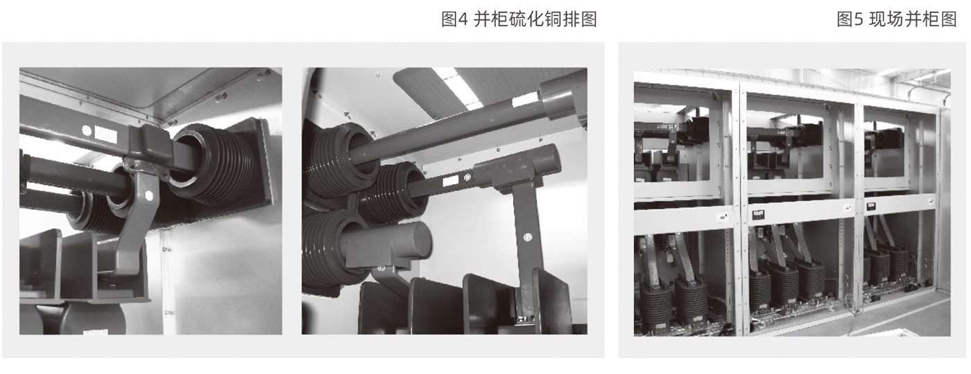
4. Employing thermal shrinkage insulation materials and epoxy coating insulation methods (Figure 3), the electrode structure has been optimized to make the enclosure structure more compact and reduce its footprint.
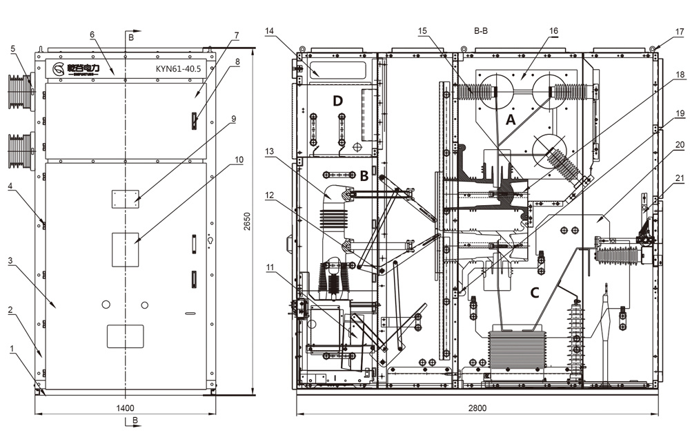
Figure 1: Schematic Diagram of the Standard Switchgear Structure
A. Busbar Room B. Handcart Room C. Cable Chamber D. Relay and Instrument Compartment
(1) Base (2) Cabinet body (3) Handcart compartment door (4) Hinge (5) Main busbar bushing (6) Top beam (7) Instrument door (8) Door lock (9) Nameplate (10) Simulation plate (11) Secondary interlocking device (12) Live-part mechanism (13) Vacuum circuit breaker (14) Small busbar terminal compartment (15) Insulator (16) Main busbar partition (17) Contact ring (18) Upper contact box (19) Lower contact box (20) Insulating partition (21) Earthing switch
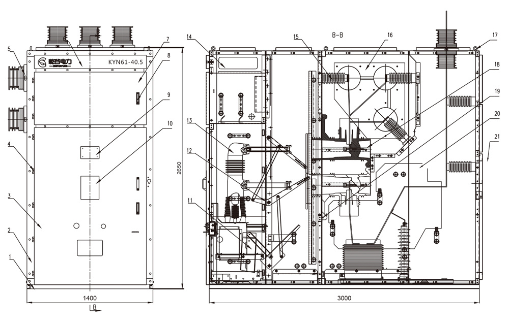
Figure 2: Schematic Diagram of the Standard Switchgear Structure
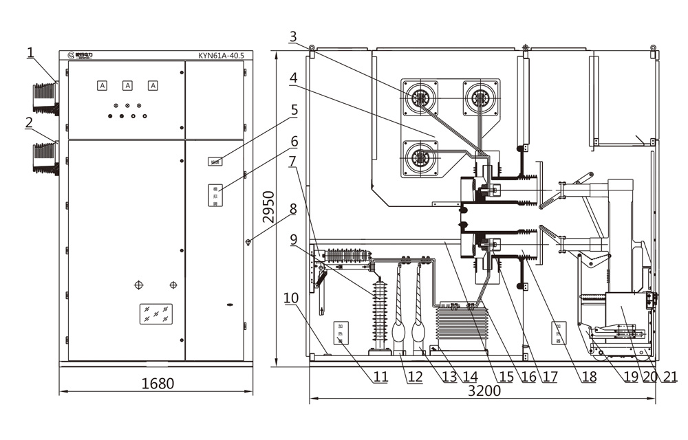
Figure 3: Schematic Diagram of the Structure of High-Altitude Switchgear
1. 1.35kV bushing 2. Cabinet assembly 3. Main busbar and branch busbar assembly 4. Main busbar partition 5. Nameplate 6. Simulation plate 7. Earthing switch 8. Sealing plate 9. Surge arrester 10. Earthing busbar assembly 11. Heater 12. Cable inlet 13. Primary high-voltage cable and cable terminations 14. Current transformer 15. Interlocking mechanism for earthing switch operation 16. Lower busbar 17. Primary static contact 18. 35kV contact box 19. Door mechanism assembly 20. Secondary socket and interlocking assembly 21. Handcart-type vacuum circuit breaker
Handcart
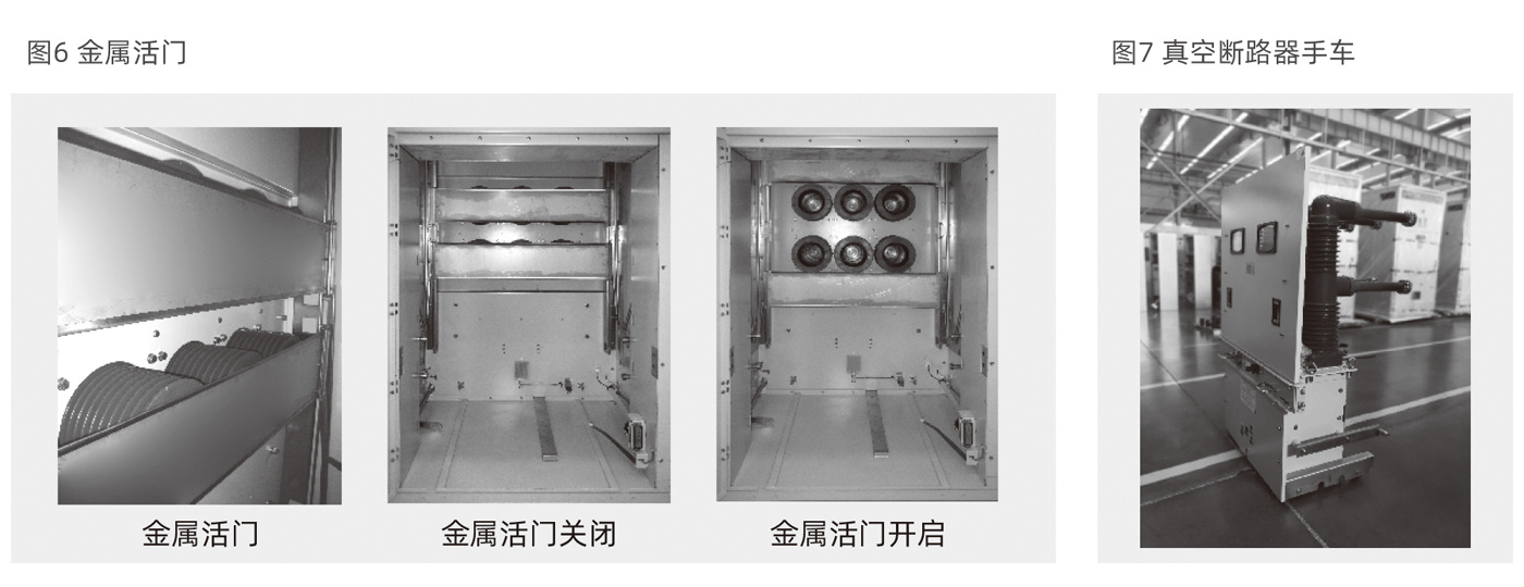
The contact box is equipped with metal shutters (Figure 6). The upper and lower shutters automatically open as the handcart moves from the disconnected/test position and automatically close when the handcart moves in the opposite direction, thereby effectively isolating it from high-voltage components. The handcart frame is fitted with a lead screw-nut actuation mechanism and an overrunning clutch. The lead screw-nut actuation mechanism allows for easy movement of the handcart between the disconnected/test position and the working position. Thanks to the self-locking feature of the lead screw-nut assembly, the handcart can be reliably locked in the working position, preventing accidental movement caused by electromagnetic forces and thus avoiding potential accidents. The overrunning clutch comes into play when the handcart is moved back to the disconnected/test position or the working position, automatically disengaging the operating shaft from the lead screw shaft and allowing it to idle freely, thereby preventing damage to the actuation mechanism due to misoperation. Additionally, a handcart position indicator can be installed; when the handcart reaches the test or working position, its corresponding position indicator light will illuminate, clearly indicating the handcart’s current location. Furthermore, the circuit breaker handcart can only be closed when it is in the test or working position, and the handcart can only be moved if the circuit breaker is in the open position.
Interlocking mechanism
1. The switchgear’s operation panel is equipped with informative operation and indication components to prevent accidental tripping or closing of the circuit breaker.
2. The vacuum circuit breaker (Figure 7) can only be closed when it is in the test position or the working position. Once the circuit breaker is closed, no further switching operations—neither closing nor opening—are permitted, thereby preventing the insertion or removal of the isolating plug under load.
3. The grounding switch shaft is equipped with an interlocking stop block, and the handcart features an interlocking plate for the grounding switch. The grounding switch can only be closed when the handcart is in the test position and the interlocking plate is in the released position. After the grounding switch is closed, the stop block prevents the interlocking plate on the handcart from entering, thus preventing the handcart from being manually shaken into the working position. When the handcart is in the working position, the handcart’s grounding switch interlocking plate remains locked in the interlocked position, making it impossible to depress the operating handle of the grounding switch. This effectively prevents closing the grounding switch while live and avoids accidentally closing the circuit breaker when the grounding switch is already closed.
4. When the grounding switch is in the open position, the cable room door cannot be opened, thereby preventing accidental entry into a live compartment.
When the circuit breaker handcart is in the test or working position and there is no control voltage, it can only be manually tripped but not closed.
When the circuit breaker handcart is in the working position, the secondary plug is locked and cannot be pulled out.
Interlock between the secondary plug and the handcart position
The connection between the secondary wiring on the switchgear and the secondary wiring on the circuit-breaker trolley is established via a manual secondary aviation plug. The secondary aviation plug is connected to the circuit-breaker trolley through a nylon corrugated conduit. The secondary aviation socket is installed at the lower left corner of the trolley compartment in the switchgear cabinet. The circuit-breaker trolley can only be plugged into or disconnected from the secondary aviation connector when it is in the test/disconnect position. When the circuit-breaker trolley is in the working position, the mechanical interlock mechanism locks the secondary aviation plug, preventing it from being disconnected. (Figure 8)
Figure 8: Circuit Breaker Handcart Installation Process

Live-display device
If the user has specific requirements, the switchgear can be equipped with a live-display device that monitors the operating status of the primary circuit. This device consists of a high-voltage sensor and a portable display unit, which are connected via wires to form an integrated system. Not only does this device indicate whether the high-voltage circuit is energized, but it can also work in conjunction with an electromagnetic lock to achieve forced interlocking, thereby preventing the closing of the grounding switch while the circuit is energized and preventing unauthorized entry into energized compartments, thus enhancing the error-proofing performance of the associated equipment.
Temperature Control and Condensation Prevention Device
To prevent the dangerous formation of condensation in climates with high humidity or significant temperature fluctuations, heaters are installed separately in the circuit breaker compartment and the cable compartment. Additionally, a temperature controller can be configured to work in conjunction with the heaters as required, enabling automatic monitoring via temperature and condensation sensors.