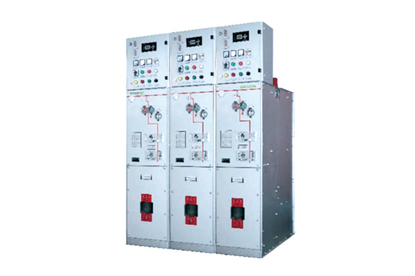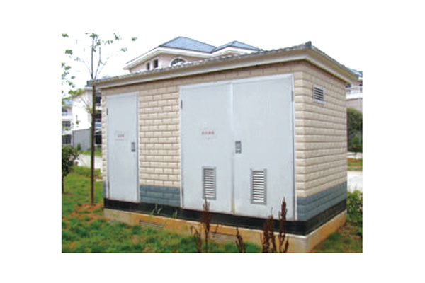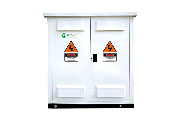
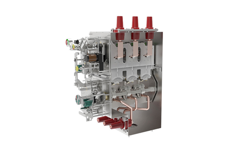
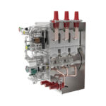
The arc-extinguishing chamber employs a vacuum interrupter, and the vacuum arc-extinguishing chamber is encapsulated in epoxy resin to form a solid-insulated pole. The wall-through solid-insulated pole is installed horizontally. The moving end of the pole is connected to the outgoing terminal via a flexible connection, while the stationary end of the pole is linked to the pivot point of the disconnecting switch’s moving blade. This arrangement effectively separates the disconnecting switch and the earthing switch into two independent compartments, ensuring that the circuit breaker can be safely maintained even when de-energized. This product features a novel design, a compact structure, long service life, reliable operation, small size, convenient operation and maintenance, and high safety.
1. The product components feature modular design, and the cabinet’s “five-protection” system is simple, reliable, and consistent.
2. The arc-extinguishing chamber circuit is encapsulated using high-quality epoxy resin material. The partial discharge level of each encapsulated pole is ≤5 pC (at 45 kV), enhancing the circuit breaker’s adaptability and reliability in harsh environments and ensuring maintenance-free operation throughout its service life.
3. The integrated design of the isolating switch, circuit breaker switch, and grounding switch results in a high-voltage vacuum circuit breaker with a clearly visible isolation gap.
4. The panel features a single-line analog marking design that is simple and easy to understand, helping to prevent accidental operation.
5. A current transformer can be installed on the outgoing side of the switchgear, allowing for a smaller cabinet or packaged substation size.
6. It can be equipped with a smart online monitoring unit and diagnostic system; the operating status of the switch can be remotely accessed via a communication module.
The indoor high-voltage AC vacuum circuit breaker with isolation features is equipped with sophisticated mechanical and electrical interlocking devices, ensuring exceptionally high operational reliability and a long service life. When paired with the corresponding outdoor switchgear, it can reliably perform safe power distribution functions, thereby guaranteeing the safety of both operators and equipment.
Altitude: ≤5000m (When the operating altitude of the equipment exceeds 2000m, this must be specifically noted);
Ambient temperature: Maximum temperature +50℃, minimum temperature -50℃, average value within 24 hours ≤35℃;
Environmental humidity: Average relative humidity over 24 hours ≤ 95%; average monthly relative humidity ≤ 90%.
Electromagnetic interference: The amplitude of electromagnetic interference induced in the secondary system ≤ 1.6 kV;
Installation environment: The surrounding air contains neither explosive nor corrosive gases, and the installation location is free from frequent, severe vibrations or shocks.
Note: If the operating environment conditions exceed those specified above, please consult our company to arrange a customized solution.
· Common technical requirements shared by IEC62271-1:2017 and GB/T11022-2020—Standard for High-Voltage Switchgear and Control Equipment
· IEC62271-200:2011 and GB/T3906-2020 3.6 kV to 40.5 kV AC metal-enclosed switchgear and control equipment
· IEC 62271-100:2017 and GB/T 1984-2014 AC High-Voltage Circuit Breakers
· IEC62271-105:2021 and GB/T16926-2009 AC High-Voltage Load Break Switch-Fuse Combination Apparatus
· IEC16271-102:2001+A1:2011 and GB/T1985-2014 High-voltage AC isolating switches and earthing switches
· IEC60529 and GB/T4208-2017: Enclosure Protection Ratings (IP Codes)
· GB/T11023-2018 Test Method for Gas Sealing of Sulfur Hexafluoride in High-Voltage Switchgear
· DL/T402-2016 Technical Specifications for Ordering High-Voltage AC Circuit Breakers
· DL/T486-2021 Technical Specifications for Ordering High-Voltage AC Disconnect Switches and Earthing Switches
· DL/T403-2017 Technical Specifications for Ordering 12kV~40.5kV High-Voltage Vacuum Circuit Breakers
· DL/T404-2018 3.6 kV to 40.5 kV AC Metal-Enclosed Switchgear and Control Equipment
· DL/T593-2016 Common Technical Requirements for Standards of High-Voltage Switchgear and Control Equipment
|
Implementation standard GB/T 1984 |
||||
|
Insulation level |
||||
|
Rated voltage |
|
KV |
40.5 |
|
|
Rated frequency |
|
Hertz |
50 |
|
|
Rated insulation level |
Power-frequency withstand voltage (phase-to-phase, phase-to-ground, vacuum interrupter contacts) |
KV |
95 |
|
|
|
Power-frequency withstand voltage (isolated break) |
KV |
118 |
|
|
|
Power-frequency withstand voltage (auxiliary and control circuits) |
KV |
2 |
|
|
|
Lightning impulse withstand voltage (phase-to-phase, phase-to-ground, vacuum interrupter) |
KV |
185 |
|
|
|
Lightning Impulse Withstand Voltage (Isolation Break) |
KV |
215 |
|
|
Current level |
||||
|
Rated current |
A |
630, 1250 |
||
|
Rated short-time withstand current |
KA |
25, 31.5 |
||
|
Duration |
S |
4 |
||
|
Rated peak withstand current |
KA |
63, 80 |
||
|
Rated short-circuit breaking current |
Fault protection |
KA |
25, 31.5 |
|
|
Rated short-circuit making current |
Short-circuit closing |
KA |
63, 80 |
|
|
Action time |
||||
|
Trip time |
|
S |
<60ms |
|
|
Closing time |
|
S |
<45ms |
|
|
Circuit breaker life (GB/T 1984) |
||||
|
Mechanical life |
M1: 2000 times |
|
M1 |
M2 |
|
M2: 10,000 times |
|
|
● | |
|
Electrical life |
E1 |
|
E1 |
E2 |
|
E2 |
|
|
● | |
|
Operation Sequence (Auto Reclosing) |
|
|
|
|
|
Operation Sequence |
|
|
There is |
|
|
Fault trip |
Manual trip release |
|
There is |
|
|
Fast switching |
Electrically operated trip/release mechanism |
|
|
|
|
Auto-reclosing |
|
|
0-0.3s-C0-180s-C0 |
|
|
Manual |
|
|
There is |
|
|
Electrical/Remote Operation |
|
|
Optional |
|
|
Closing speed |
|
m/s |
1.4–2.0 |
|
|
Trip speed |
|
m/s |
0.8~1.2 |
|
|
Closing time (rated voltage) |
|
m/s |
30~70 |
|
|
Trip time (rated voltage) |
|
m/s |
20~50 |
|
|
Circuit resistance |
|
microohm |
≤80 |
|
|
Serial number |
Name |
Unit |
Data |
|
|
1 |
Rated voltage |
KV |
40.5 |
|
|
2 |
1-minute power frequency withstand voltage (RMS value) |
KV |
95 |
|
|
3 |
Lightning impulse withstand voltage (peak) |
KV |
185 |
|
|
4 |
Rated frequency |
Hertz |
50 |
|
|
5 |
Rated current |
A |
1250/1600/2000/2500 |
|
|
6 |
Rated short-time withstand current |
KA |
20/25/31.5 |
|
|
7 |
Rated peak withstand current |
KA |
50/63/80 |
|
|
8 |
Rated short-circuit duration |
s |
4 |
|
|
9 |
Rated short-circuit breaking current |
KA |
20/25/31.5 |
|
|
10 |
Rated short-circuit making current |
KA |
50/63/80 |
|
|
11 |
Rated operating sequence |
|
O-0.3s-CO-180s-CO |
|
|
12 |
Break time |
Ms. |
<80 |
|
|
13 |
Rated short-circuit breaking current number of breaking operations |
Next |
20 |
|
|
14 |
Single capacitor bank breaking current |
A |
630 |
|
|
15 |
Breaking current of back-to-back capacitor banks |
A |
400 |
|
|
16 |
Rated operating voltage |
V |
AC/DC 110, 220 |
|
|
17 |
Mechanical life |
Next |
10000 |
|